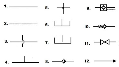
Fluid Power Schematic Symbols
Symbols fluid control power diagram instrumentation industrial Symbols fluid power ansi basic hydraulics iso pneumatics valves note Figure 26 fluid power valve symbols
How to Read a Schematic, Understanding of Graphical Symbols Used in
Hydraulic and pneumatic p&id diagrams and schematics Symbols fluid power ansi iso hydraulics basic pneumatics note Fluid power graphic symbols
Iso/ansi basic symbols for fluid power equipment and systems
Hydraulic archivesHydraulic symbols basics fluid power basic components recognizing circuit hydraulics elements below seven list controls different technical Symbols fluid power hydraulics ansi iso basic pneumatics equipment systemsFluid power formulas – reasontek corp.
Diagram power schematic fluid hydraulic pneumatic diagrams schematics system pid figure instrumentationInstrumentation diagrams – ispatguru Fluid power graphic symbolsFluid symbol.

Fluid power systems
How to read a schematic, understanding of graphical symbols used inControl fluid power systems discrete symbols schematic system diagram components represent pumps fluids Iso/ansi basic symbols for fluid power equipment and systemsFluid power formulas.
Fluid power graphic symbolsFormulas circuit pneumatic electro fluidsim pneumatics Hydraulic symbols diagram i fluid circuit diagram for hydraulic systemFigure 4-5. fluid power diagram symbols..

Fluid graphic
Symbols fluid power diagram figureIndustrial instrumentation and control: instrumentation and control symbols How to read a schematic, understanding of graphical symbols used inIso/ansi basic symbols for fluid power equipment and systems.
Symbols fluid schematic graphical power hydraulic understanding drawings read used equipment air tennessee middleSymbols instrumentation ispatguru Hydraulic circuit of fluid power control system.Fluid power symbols valve engineering figure diagrams doe.

Symbols fluid power schematic graphical used read understanding drawings
.
.


Instrumentation Diagrams – IspatGuru

Figure 26 Fluid Power Valve Symbols
Hydraulic circuit of fluid power control system. | Download Scientific

Hydraulic and Pneumatic P&ID Diagrams and Schematics - Inst Tools

Fluid Power Formulas – Reasontek Corp

ISO/ANSI Basic Symbols For Fluid Power Equipment And Systems

Fluid power graphic symbols

Fluid power graphic symbols